Master-Touch™ Multipoint Systems
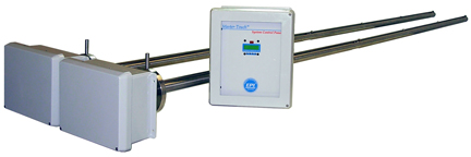
Eldridge Products, Inc. (EPI) Series 9000MP Multipoint Thermal Mass Flowmeter Systems are designed to measure air and gas flow in Thermal Mass Flowmeter Systems where two or more sensing points are required due to large cross-sectional areas. The Series 9000MP Multipoint Thermal Mass Flowmeter System now incorporates our newest Master-Touch microprocessor technology. This advancement provides the user with unrivaled control, power, and flexibility for measuring flows in large ducts, stacks, and flow conduits. The Series 9000MP Multipoint Thermal Mass Flow Meter Systems have a sensor accuracy of ± (1% of reading + .5% of full scale) over a calibration turndown ratio of 100:1 or more, based on velocities as low as 15 SFPM (.076 NMPS) and as high as 20,000 SFPM (101.6 NMPS).
Eldridge Products, Inc. (EPI) Series 9000MP Multipoint Thermal Mass Flowmeter Systems are designed to measure air and gas flow in Thermal Mass Flowmeter Systems where two or more sensing points are required due to large cross-sectional areas. The Series 9000MP Multipoint Thermal Mass Flowmeter System now incorporates our newest Master-Touch microprocessor technology. This advancement provides the user with unrivaled control, power, and flexibility for measuring flows in large ducts, stacks, and flow conduits. The Series 9000MP Multipoint Thermal Mass Flow Meter Systems have a sensor accuracy of ± (1% of reading + .5% of full scale) over a calibration turndown ratio of 100:1 or more, based on velocities as low as 15 SFPM (.076 NMPS) and as high as 20,000 SFPM (101.6 NMPS).
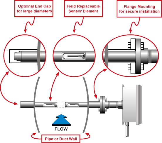
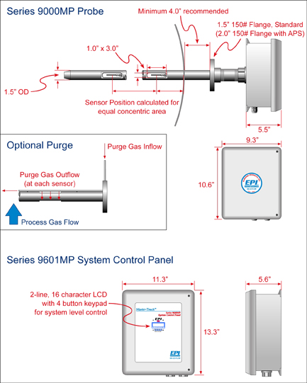
Each Series 9000 Multipoint Thermal Mass Flowmeter System includes the Series 9000MP Flow Transmitter probe assembly and the Series 9600MP Thermal Mass Flow Meter System Control Panel. The flow transmitter probe assembly is the heart of the Series 9000 Multipoint Thermal Mass Flowmeter System. The probe assembly consists of two or more flow sensors (maximum of 5 sensors per probe) mounted in a 1½” OD probe shaft. Each sensor is matched to its own bridge board and is individually calibrated and linearized. The bridge board and microprocessor for each sensor are mounted outside of the flow duct in an enclosure at the end of the probe shaft.
The voltage output from each sensor and bridge board set is sent to its own Master-Touch microprocessor board for accurate linearization of the flow rate signal. The linearized output signals from the multiple sensors in the probe are then averaged by a summer/averager module (Option 140). Typically, the probe assembly’s averaged output signal is transmitted to the remote Thermal Mass Flow Meter System control panel for grand averaging with the signals from other probe assemblies. However, flow transmitter assemblies may be specified with either one average output signal and/or individual signals to allow individual sensor readings at the Thermal Mass Flowmeter System control panel.
Individual sensor and bridge board sets may be periodically tested at the probe location to verify performance. If one or more sets are not functioning as required, they may be removed from the probe signal average by removing the sensor input wire and turning off a DIP switch on the averager board without affecting overall Thermal Mass Flow Meter System operation. The individual sensor and bridge board sets are field replaceable without complete probe disassembly.
Multipoint System
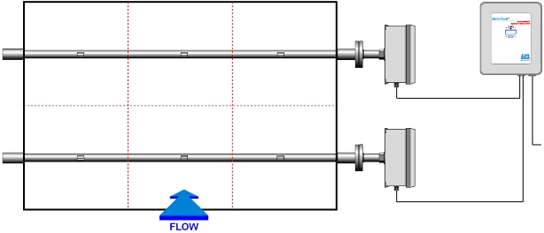
The chart below is a guideline to the number of traverse points suggested for a circular duct. Once the average flow rate is determined, the factory can specify the minimum number of sensors in a Series 9000 Multipoint Thermal Mass Flowmeter System. The greater the number of points measured, the greater the accuracy of the final average flow rate. Also note that the accuracy of any one point becomes of less importance to the final accuracy of the total flow rate as the number of points is increased because of the averaging method utilized. If the point of average flow cannot be determined, then a simple rule is to specify the number of points based on the chart below.
| Duct Diameter | Suggested Number of Probes | Suggested Sensors per Probe | Total Number of Sensors |
| 8″ – 18″ | 1 | 2 | 2 |
| 18″ – 24″ | 1 | 4 | 4 |
| 24″ – 36″ | 2 | 2 | 4 |
| 36″ – 60″ | 2 | 4 | 8 |
The Series 9600MP Thermal Mass Flow Meter System Control Panel is housed in a 16″ x 14″ NEMA 4X fiberglass enclosure (NEMA 7 optional). This enclosure holds the power supply, Option 141 averager board (required for Thermal Mass Flowmeter Systems with multiple probe assemblies), and a microprocessor board for control of the overall Thermal Mass Flow Meter System output signal, and can be located from as little as a few feet to as much as thousands of feet from the transmitter probe assemblies. The control panel provides the power for the probe assemblies over a two wire electrical connection. The flow transmitter sends its signal to the control panel over a 4 – 20 mA signal loop. This method requires a four wire connection per probe assembly (power supply positive, power ground, 4 – 20 mA average output and return). The control panel provides two analog output signals (0 – 5 VDC and 4 – 20 mA) linearized proportionally to the grand average flow rate, as well as two digital interfaces (RS232 and RS485). The 4 – 20 mA grand average output can drive up to 1200 ohms.
Purge System
The Eldridge Air Purge System (APS) provides a means of cleaning the sensors in applications where particulates cause problems. A stainless steel tube is mounted on the downstream side of the probe support with a pair of outlet holes positioned at each sensor. The tube is connected to a tap located on the mounting flange. After basic installation of the multipoint system is complete, a pressurized gas line (typically compressed air) is connected to the tap. The gas is released at set intervals to clean the sensor surface of any accumulated particulates. The frequency and duration of the purging gas stream can be controlled by the multipoint system’s relays based on elapsed flow or by an external timing device supplied by the customer.
Master-Touch™ Technology
The addition of our Master-Touch technology to the Series 9000 Multipoint Thermal Mass Flowmeter System provides the user with unparalleled control over the Thermal Mass Flow Meter System’s operation. Our Master-Touch microprocessor includes five major Thermal Mass Flowmeter Systems to enhance the performance of our proven thermal technology:
- Analog-to-Digital Converter to acquire data generated from sensors.
- Curve Linearizer to transform nonlinear to linear voltages.
- Digital-to-Analog Converter to generate output voltage from sensor data.
- Voltage Tracking to perform real-time processing of input and output signals.
- EEPROM to store and maintain user configurable variables.
The basic Series 9000 Multipoint Thermal Mass Flow Meter System configuration includes a Master-Touch LCD display in the Series 9600MP Thermal Mass Flowmeter System control panel. This 2-line, 16 character display and 4-button keypad provide access to the Master-Touch features to monitor the averaged Multipoint Thermal Mass Flow Meter System flow data. Optionally, an LCD display and 4-button keypad can be added for each microprocessor in the probe assembly to give unprecedented control over the operation of each sensor. Access to the Master-Touch features is also available via RS232 communications between the Master-Touch and a laptop or PC.


